Sulphur hexafluoride (SF6) tracer technique
Arjan Jonker 2
Peter Moate 3
Amelie Vanlierde 4
Cécile Martin 1
1 Université Clermont Auvergne, INRAE, Saint-Genès-Champanelle, France
2 AgResearch Limited, Palmerston North, New Zealand
3 Agriculture Victoria Research, Ellinbank, Australia
4 Walloon Agricultural Research Centre, Gembloux, Belgium
Keywords
permeation tube, gas sampling, vacuum pump, canister, release rateIntroduction
A further method for measuring methane production is the sulphur hexafluoride (SF₆) tracer technique, which requires inserting a known quantity of the inert tracer into the rumen [1]. The use of the SF₆ tracer technique to quantify enteric CH₄ emissions from grazing ruminants was pioneered by Zimmerman [2] and Johnson [1]. The SF₆ tracer technique is an indirect method to quantify CH₄ emissions from ruminants because only a representative quantity of gas produced by the animal is collected; the emissions are not quantitatively captured as occurs with the respiration chamber (RC) technique, which is the ‘gold standard’ method. Sulphur hexafluoride is considered an ideal tracer gas because it has similar dispersion characteristics in the rumen as CH₄; it is not toxic for the rumen microbes nor the animal and can be measured at very low (trace) amounts. Historically, the SF₆ tracer method generated data with high variability; however, recent modifications to the technique have reduced some of the sources of systemic error and thus the tracer technique can be used with a high degree of accuracy and precision comparable to (RC) [3].
Prerequisites
The purpose of the present guideline is to provide key elements and steps for implementing this technique based on the technical manual of Johnson [4]. More detail on the technique is compiled in guidelines available on the web site of the Global Research Alliance (https://globalresearchalliance.org/publication-library/?doctype=223&research-group=212).
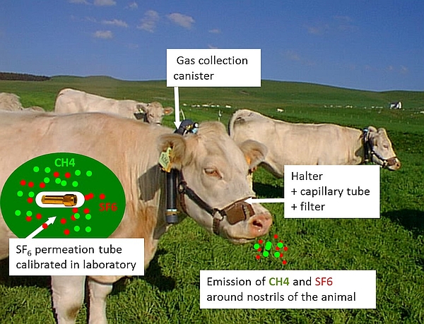
The SF₆ tracer technique relies on the release of a known quantity of SF₆ tracer gas (mg/d) from a pre-calibrated permeation tube inserted into the reticulo-rumen (Figure 1). The ratio of gas concentrations ([CH₄] in ppm/[SF₆] in ppt) of representative breath gas samples, that are collected around animals' nostrils into a canister via a sampling line system and adjusted for concentrations in background air (BG), is used to calculate daily CH₄ production (g/d) as follows (MWCH₄ = 14 g for the molecular weight of CH₄ and MWSF₆= 146 g for the molecular weight of SF₆):
\(CH_\textit4 \text { (g/d)}=SF_\textit6 \text { release rate (mg/d)} \times \frac {CH_\textit4-CH_{\textit4\_\textit background} } {SF_\textit6-SF_{\textit6\_\textit background}} \times \frac {MWCH_\textit4} {MWSF_\textit6} \times 1000\)
The use of the SF₆ technique is labour-intensive and requires trained staff with skills for preparing calibrated devices (SF₆ permeation tube, gas collection system), for fitting and exchanging collection devices on animals, and for gas analyses in laboratory. We recommend allowing a preparation period of 6 months before the start of a first trial using this technique, and 3 months for a routine trial, which includes time for tube construction and calibration.
A – The SF₆ permeation tube and its calibration
- Accurate determination of the SF₆ release rate from the permeation tube is crucial for the calculation of daily CH₄ emissions. This parameter is obtained by calibrating each permeation tube in a laboratory during a minimum of 2 months.
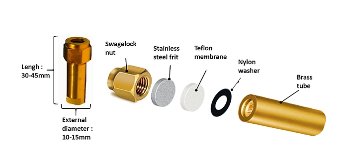
- The SF₆ permeation tube is constructed from a brass body which must be clearly, indelibly and uniquely identified (letter, numbers, etc.). On the open end, the outside of the brass tube is threaded for attachment of a Swagelok nut with a stainless-steel frit, a Teflon membrane and a nylon washer as detailed in Figure 2. Maintaining this sequence of the different components is crucial. The thickness of Teflon membrane (0.12–0.40 mm) dictates the permeation rate of SF₆ from the permeation tube. The function of the frit (2 µm pores) is to protect the Teflon membrane against internal pressure, and the function of the nylon washer (0.7 mm-thick) is to avoid teflon deformation when tightening the Swagelok nut.
- Before assembly, all components of the permeation tube are cleaned with acetone. From this point on, construction of the tubes is done with laboratory gloves to avoid contamination with residues (moisture, oil). After assembling the different components, an electronic scale, fitted with an enclosure to prevent interference from air currents, is used to weigh the permeation tube to determine its initial empty weight to an accuracy of 0.00001 g.
- To load the tube with SF₆, the permeation tube body is cooled by partial immersion in liquid nitrogen (−196°C) and filled with pure SF₆ gas directly from a cylinder. The quantity of SF₆ loaded (600–2,500 mg for 0.5–2.0 ml internal volume available, respectively) depends of the size of the permeation tubes (~10–15 mm external diameter; 40–45 mm length). The SF₆ gas condensates into solid form when transferred into the cavity of the tube. The tube is immediately capped with a Swagelok nut and the other parts (frit, Teflon, washer), and tightened manually with a standardized torque (5–7 Nm). It is necessary to re-torque the nut as the tube warms to ambient temperature, and before weighing, to determine the exact quantity of SF₆ loaded into the tube [3].
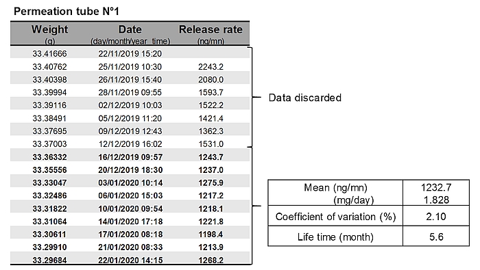
- Each permeation tube is gravimetrically calibrated by weighing once or twice weekly over 6–10 weeks. The tubes are maintained in a ventilated incubator at 39°C during the calibration period. The decrease in the weight of tubes over time allows determining the SF₆ release rate of each tube. Generally, weight changes are inconsistent in the first weeks after tube construction, and these data are discarded. Data are fitted with linear or non-linear approach [6]. Only permeation tubes with a R2>0.999 are used for animal trials (Figure 3).
- If not used immediately, calibrated permeation tubes can be stored at −80°C, until required with no change in release rate or pattern of SF₆ release [7]. After thawing, release rates of permeation tubes can be checked gravimetrically during 3–4 weeks before beeing used to confirm that the release rate is still the same as during the calibration.
- Reported release rates of SF₆ from permeation tubes used for cattle varied between 1 and 7 mg/d, depending of their size. The use of permeation tubes with small range in release rate (CV = 15–20%) is recommended for a specific trial. In a direct comparison, Martin [8] reported that the SF₆ tracer techniques had better performances to quantify CH₄ emissions on cows with low release rate permeation tubes (1.6 mg/d) than the ones with high release rates (3.2 mg/d). However, permeation tubes with high SF₆ release rate (>4 mg/d) are more widely used because they result in concentrations of SF₆ in breath gas samples that are much larger than SF₆ concentrations in the background gas samples.
B – The gas sampling device and its calibration
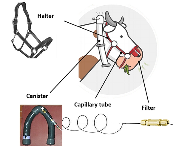
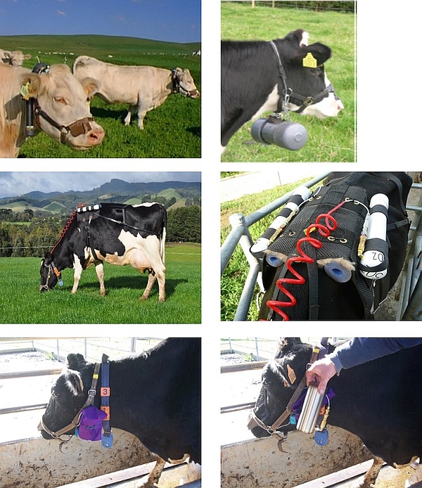
The gas sampling system consists of an evacuated canister connected to a sampling line with a calibrated flow restrictor (e.g. capillary tube) and a filter, fitted and attached to a modified halter to keep the sampling point at the muzzle (Figure 4).
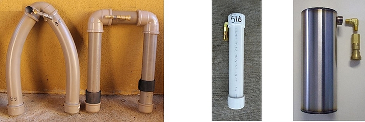
- Various designs of canisters exist in terms of shape (V-shaped, U-shaped, cylindrical; Figure 5), volumes (0.5–5 l) and material (PVC, stainless steel). All canisters are equipped with a quick connect from Swagelok to attach the sampling line. The location of the collection canister on the body of the animal may also vary (neck, back, chin, cheek; Figure 6). The final material chosen and its location on the animal will be adapted to the experimental conditions in order to limit disrupting animal behaviour and the risk of material breakage. For example, a canister positioned on the neck, chin or cheek is not appropriate for ruminants eating from bins or gates. The number of canisters required for an experiment is at least 2.5 times the number of experimental animals per study.
- Each canister needs to be tested for leaks before each trial. This can be done by evacuating the canister with a vacuum pump (−0.9 ATM), recording the vacuum and checking the vacuum again after at least 24 h. A decline in vacuum of more than 5% after 24 h suggests the canister is leaking and needs repairing and rechecking before use.
- Sampling flow restriction: The flow restrictor controls the flow rate of air into the vacuum canister (initial vacuum −0.9 ATM) so that the desired flow rate results in the canister being approximately half-filled with air (−0.40/−0.50 ATM) by the end of the collection period (24 h in most cases). The calibrated flow rate required, is dependent on the volume of the canister used and duration of the collection period.
- Different flow restrictors have been used to regulate the airflow to the canister [9]: a stainless steel capillary tube in which the length determines the flow rate [1], a short length capillary tube which is crimped to achieve the desired flow, ball bearing [10], stainless steel orifice plate, which has a fixed diameter to restrict the flow [9].
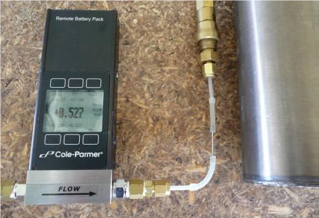
- Calibrating the flow rate of a flow restrictor (capillary tube crimped or coiled, ball bearing) is done by connecting the sampling line to an evacuated canister (−0.9 ATM) on one side and a flow meter on the atmospheric side (Figure 7). The reading of the air inlet in the canister is displayed on the flow meter screen when opening the evacuated canister. The flow rate of orifice plates cannot be adjusted, but plates with various diameters (i.e. flow rates) are available to suite canisters with different volumes.
- Filter: The purpose of the filter is to protect the flow restrictor from blockages with dust or water. A silicone tube is added on the filter as the last part of the sampling line. This silicone tube is meant to protect the filter and to better adjust the sampling site of the gases emitted by the animal. Sometimes, this tube can have a Y-shape to be closer to each nostril.
- Halter: The size of the halter must be adapted to the size of the head of the animal. The halter is a support for attaching the sampling line, including the filter positioned on a leather nose platform.
- Testing of the complete gas collection device: All components of the collection device are assembled and tested in laboratory for leaks before using on animals. For that, a canister can be evacuated, the vacuum measured (and recorded) and then the vacuum recorded again after a week. If a leak has occurred, the canister will have lost some vacuum. Alternatively, a canister is pressurized with pure nitrogen over atmospheric pressure (1.5 ATM) and submerged in water to identify the location of the leaks with bubbles appearing along the system.
- Extra-material: It is important to have additional canisters as mentioned above and halters with sampling lines (+25%) to replace leaking canisters or broken sampling lines throughout the SF₆ trial.
C – Adaptation period
Permeation tubes are dosed during the adaptation period and animals are adapted to wearing the sampling system prior to the start of breath sample collection.
- It is imperative that the identification numbers of the SF₆ permeation tube and the corresponding animal are recorded. The permeation tube is orally dosed into the rumen at least 7 d before breath sampling starts. This ensures good homogenization of the SF₆ and other fermentation gases. One should observe the animals to make sure they do not spit out the permeation tube in the minutes after dosing.
- Usually 2 d before the start of gas collection period, animals are fitted with ‘training’ halters and canisters for adaptation of wearing sampling gear.
D – Gas collection period
- Each animal is fitted with one sampling collection device (i.e. canister and halter with sampling line). Some research teams fit a halter with two independent sampling lines in parallel to collect two independent breath gas samples per d per animal. Initial pressure of each pre-evacuated collection canister and time of connection with the sampling line are recorded. The best time to initiate a gas collection period is before feeding, when CH₄> production is low. Canisters are exchanged around the same time every day during gas collection periods.
- A similar protocol is followed for canisters used for background air sampling. Several background canisters are placed in the environment where the animal is housed or grazing (minimum 3 sampling systems preferably placed at the same height as the animals nostrils). An alternative approach has been, to put one background canister on each animal (on the back of the animal as breath sampling canister), which is especially advisable in measurement environments with variable background gas concentrations (e.g. in many types of indoor facilities and under windless conditions). However, this method doubles the number of gas samples for analyses. The SF₆ tracer technique should not be used in a poorly ventilated building and with high animal density.
- At the end of the gas collection period (24 h in most cases), the canisters are removed from the animal (and the backgrounds) and the post-collection vacuum is recorded. Two scenarios can arise: (a) a proper pressure: at a residual vacuum of between 30 and 70%, a new canister is fitted on the animal (and for the background); (b) an improper pressure <30% or >70% vacuum indicates a leak or a blockage, respectively, in the collection device. In both cases, the full system (halter and canister) must be replaced by a new one, and the broken system has to be repaired (leak, blockage).
- Daily collection of gas is repeated on 4–7 consecutive days to have at least 3–4 good samples for daily CH₄ measurements [11]. Total duration of the gas collection period depends on the experimental conditions (indoors, outdoors) and the risk of failing to collect representative gas samples (quantity and quality). Additional days can be added if required.
E – Gas analysis in laboratory
After gas collection into canisters (breath and background), the concentrations of CH₄ and SF₆ are analysed using a gas chromatograph (GC), fitted with a flame ionization detector and an electron capture detector, respectively. Two different approaches are used to inject the gas collected from the canister into the GC [9]:
- Injection of gas after dilution with nitrogen: each collection canister (−0.5 ATM) is over-pressurized with high-purity nitrogen gas over standard atmospheric pressure (i.e. 2–1.5 ATM). After 1–2 h, a stable gas mix is formed and the diluted gas can be (1) directly injected into the GC via sample loop connected to the canister or (2) sub-sampled with a syringe into glass vials through a glass sub-sampling port, attached to Swagelok quick-connect before injection in the GC.
- Injection of gas without prior dilution with nitrogen: the gas is extracted from the canister into vials using a piston and a vaccum pump according to different systems. This eliminates the need for dilution and therefore improves the analytical accuracy by strengthening the GC signal to noise ratio.
- A general recommendation is that GC analyses should be done as soon as possible after gas sampling. This allows to check the quality of the gas samples collected during the period and to change the collection device on the animal or extent the collection period if necessary. Otherwise, gas collected can be stored for several weeks without problems for later analyses.
- After gas analysis, all canisters are cleaned by evacuation to remove residual gas and flushed with nitrogen before evacuation in preparation for reuse. It is recommended that specific canisters are dedicated for sampling on animals and others for background in order to avoid cross-contamination.
F – Calculation to estimate daily CH₄ emissions
After GC analysis of gas samples, all trial data needs to be combined and screened for abnormal values to exclude before statistical analysis.
At the end of the trial, all the material should be cleaned by repeated flushing (2–3 times) with nitrogen gas to remove residual CH₄ or SF₆ gases, checked for leakages or blocking, and stored in slight overpressure with nitrogen gas in a dry and well-ventilated room.
References
[1] Johnson K, Huyler M, Westberg H, Lamb B, Zimmerman P. Measurement of methane emissions from ruminant livestock using a sulfur hexafluoride tracer technique. Environ Sci Technol. 1994;28(2):359-62. DOI: 10.1021/es00051a025[2] Zimmerman PR [inventor]; Univ. Corporation for Atmospheric Research [assignee]. System for Measuring Metabolic Gas Emissions from Animals. US5265618A. 1993.
[3] Deighton MH, Williams SRO, Hannah MC, Eckard RJ, Boland TM, Wales WJ, et al. A modified sulphur hexafluoride tracer technique enables accurate determination of enteric methane emissions from ruminants. Anim Feed Sci Tech. 2014;197:47-63. DOI: 10.1016/j.anifeedsci.2014.08.003
[4] Johnson KA, Westberg HH, Michal JJ, Cossalman MW. The SF₆ technique: methane measurement from ruminants. In: Makkar HPS, Vercoe PE, editors. Measuring methane production from ruminants. Dordrecht, Netherlands: Springer; 2007. p. 33-67.
[5] Lassey KR, Walker CF, McMillan AMS, Ulyatt MJ. On the performance of SF₆ permeation tubes used in determining methane emission from grazing livestock. Chemosphere. 2001;3(4):367-76. DOI: 10.1016/S1465-9972(01)00017-4
[6] Moate PJ, Ribaux BE, Hannah MC, Deighton MH, Williams SRO, Wales WJ. Michaelis–Menten kinetics predict the rate of SF6 release from permeation tubes used to estimate methane emissions from ruminants. Anim Feed Sci Tech. 2015;200:47-56. DOI: 10.1016/j.anifeedsci.2014.12.001
[7] Moate PJ, Ribaux BE, Rabl MR, Hannah MC, Deighton MH, Williams SRO, editors. Freezing and thawing permeation tubes does not alter their subsequent rate of SF6 release. 7th GAA-Greenhouse Gas and Animal Agriculture Conference; 2019; Iguassu Falls, Brazil. São Carlos, SP: Embrapa Southeast Livestock; 2019.
[8] Martin C, Koolaard J, Rochette Y, Clark H, Jouany JP, Pinares-Patiño CS. Effect of release rate of the SF(6) tracer on methane emission estimates based on ruminal and breath gas samples. Animal. 2012 Mar;6(3):518-25. DOI: 10.1017/S175173111100156X
[9] Deighton MH, Williams SRO, Moate PJ, Gere JI, Martin C, R.J M, et al. Guidelines for use of sulphur hexafluoride (SF6) tracer technique to measure enteric methane emissions from ruminants. Lambert MG, editor. New Zealand: New Zealand Agricultural Greenhouse Gas Research Centre; 2014
[10] Gere JI, Gratton R. Simple low-cost flow controllers for time averaged atmospheric sampling and other applications. Lat Am Appl Res. 2010;40:377-81.
[11] Arbre M, Rochette Y, Guyader J, Lascoux C, Gómez LM, Eugène M, et al. Repeatability of enteric methane determinations from cattle using either the SF6 tracer technique or the GreenFeed system. Anim Prod Sci. 2016;56(3):238-43. DOI: 10.1071/AN15512